Solar for IoT: A Tutorial
July 2026
What we’re building
This is a build-along guide for two specific outdoor solar-powered projects:
- A MeshCore LoRa repeater — a low-power Xiao nRF52840 board with a Wio-SX1262 LoRa radio, sitting on a hilltop or rooftop forwarding mesh packets around the clock. Draws about 10 mA on average.
- A drone-detector node — part of an unreleased fork of the drone-mesh-mapper project that routes over MeshCore. A Xiao ESP32-C5 runs WiFi and BLE in monitor mode to catch FAA Remote ID beacons from nearby drones, and a second Xiao nRF52840 + Wio-SX1262 relays detections over MeshCore to a home base station. Draws roughly 70 mA on average.
Both live outdoors year-round, charge from a solar panel during the day, and survive cloudy stretches on an 18650 battery (the standard cylindrical lithium-ion cell, 18 mm × 65 mm — Project 2 uses the slightly larger 21700 format, 21 mm × 70 mm). Neither talks to the grid and neither has a big charge controller — the whole system fits in a small junction box: a panel, a cell or two, and a postage-stamp charger IC.
The two projects are written as peers, and it’s helpful to read through both to get an idea of tradeoffs you might consider at different sizes. They share the essentials cheat sheet (next section) and the enclosure advice at the end.
A note on difficulty. Project 1 is a good first build — a panel, a couple of cells, one charger module, and maybe a dozen solder joints. Project 2 is a real step up: a custom two-board carrier PCB you order from a fab, drone-detection firmware, and a longer parts list. If this is your first solar project, build Project 1, get it running outside, then decide whether you want the rest.
Who this is for
You’re comfortable with Arduino-level electronics, know which end of a soldering iron to hold, and have built something with a battery before. You haven’t designed a power supply, and you don’t want to become an expert — you want the recipe, a parts list, and a wiring diagram, with enough context that the choices make sense. Phrases like “see Solar for IoT — Sizing from a power budget” point to the physics-first companion document for anyone who wants the why.
Tools and skills you’ll need
Nothing exotic, but before you buy parts:
- A soldering iron, and the basic skill to make a few through-hole joints. Both projects need some soldering; neither needs fine surface-mount work by hand.
- A multimeter — for polarity, continuity, and checking that a module is actually what the listing claimed. Assume you’ll reach for it more than once.
- A way to flash firmware: a USB-C cable and either the Arduino IDE or PlatformIO. Everything here programs over USB.
- Project 2 only: enough comfort with a PCB fab like JLCPCB to upload design files and pick assembly options. Never done it? Project 1 skips this entirely.
The essentials cheat sheet
Five rules do most of the work. Each one is a line of math or a single choice, with a one-sentence reason. The reference has the full derivations.
Rule 1: size the panel from the worst month
\[\text{Panel watts at STC} = \frac{\text{average load (W)} \times 24 \text{ h}}{\text{peak sun hours} \times 0.40}\]
STC (Standard Test Conditions) is the lab benchmark every solar panel is rated against — 1000 W/m² of sunlight, 25 °C (77 °F) cell temperature, and a specific reference spectrum. Real outdoor light and temperatures are almost never that. Peak sun hours is the number of hours per day equivalent to full noon sun under those lab conditions. At mid-latitudes (~35° N), December’s number is about 2.5 — plug that in, because if the panel keeps up in December it keeps up all year. The 0.40 is the “all-losses” derate (heat, dust, angle, aging, chip efficiency) that turns the lab-condition nameplate rating into what you’ll actually harvest.
See Solar for IoT — “Sizing from a power budget” — for the full derivation and the list of derating factors.
Rule 2: size the battery for the worst dark stretch
\[\text{Battery watt-hours} = \text{daily energy} \times N_{\text{dark days}} \times 1.3\]
\(N_{\text{dark days}}\) is how many
days of near-zero harvest you need to survive on battery alone; 3 for a
forgiving climate, 5–7 for a gloomy one. The 1.3 is a safety margin
(cold weather, end-of-life capacity, partial recharge after each bad
day). Usable capacity is about 80% of nameplate, so buy a cell with at
least desired Wh ÷ 0.8.
See Solar for IoT — “Protecting against over-discharge” — for why you need both a cutoff and a reconnect threshold.
Rule 3: always have a low-voltage cutoff with hysteresis
A Li-ion cell below 3.0 V is being permanently damaged. The fix is a low-voltage cutoff (LVC) — cut off around 3.0 V — paired with a reconnect threshold at least 400 mV higher (3.4–3.6 V). Without that hysteresis, you get a “brown-in loop” where the device boots, sags the battery, shuts down, recovers, and repeats — worse than a clean shutdown. Both projects here get this from the protected 18650 cell (Project 1) or a small BMS board (Battery Management System — a tiny circuit that disconnects the cell at the cutoff voltage; Project 2), plus the charger chip’s own under-voltage lockout (the chip’s built-in minimum-voltage cutoff).
See Solar for IoT — “Protecting against over-discharge” — for the three places protection can live and how to layer them.
Rule 4: keep the charge rate gentle, especially in the cold
Charge rate in “C” is the ratio of charge current to battery capacity: 1 A into a 2 Ah cell is 0.5C. Below about 0.1C, even sub-freezing charging is broadly considered safe; above about 0.5C below freezing, you plate lithium and the cell is damaged permanently. For small-panel solar this rarely needs a chip to enforce it — panel size alone keeps the rate low. For both projects below, the worst-case charge rate is around 0.15C.
See Solar for IoT — “Safe charging rates (C-rate)” — for the cold-charge nuance and field data from Canadian Rockies deployments.
Rule 5: block reverse current
At night the panel is a diode in the wrong direction and will slowly drain the battery. Modern charger chips (including the CN3791 both projects use) have this blocking built in — leakage is well under a microamp. If you were wiring a raw panel to the battery without a charger chip, you’d put a Schottky diode (a one-way valve for current — lets electrons flow panel-to-battery, blocks the reverse) in series. For this build you don’t need to.
See Solar for IoT — “Power-management chips for small devices” — for the full discussion of reverse-current options.
Sizing your own device
The two builds below are worked examples, but the five rules size anything. To do your own device instead of copying a project:
- Measure your average current. Put a multimeter — or better, a power profiler — in series with your device and watch it through a full duty cycle: sleep, wake, transmit, back to sleep. Average it. This one number drives everything downstream, so measure it rather than guess.
- Run Rule 1 with that current and your latitude’s December peak sun hours. Round the answer up to a panel you can actually buy.
- Run Rule 2 for the battery: daily energy × the dark days you want to ride out × 1.3, then divide by 0.8 for usable capacity.
- Reuse the protection pattern. A CN3791 module matched to your panel voltage, a protected cell or a 1S BMS for the low-voltage cutoff, and reverse-current blocking handled by the charger chip. That trio covers most small outdoor devices.
- Check the charge rate: panel watts ÷ battery volts ÷ battery amp-hours. Below about 0.15C you’re in the gentle regime and can stop thinking about it.
If your device pulls hard in short bursts — a cellular modem, a high-power transmit — add a buffer capacitor across the battery rail so the cell doesn’t sag. And once you need more than about ten watts of panel, you’ve outgrown this guide and want a dedicated charge controller instead.
Project 1: Xiao nRF52 MeshCore repeater
A standalone MeshCore LoRa repeater you can leave on a rooftop or pole for a year untouched. Forwards mesh packets continuously. No detector role, no ESP32 — just the LoRa radio and its mesh-routing firmware.
Power budget
| Item | Value |
|---|---|
| Average current (listen mode, nRF52) | ~10 mA @ 3.3 V |
| Average power | ~33 mW |
| Daily energy | ~800 mWh |
| Winter sun hours (35° N) | 2.5 |
| Required panel rating (rule 1) | 800 mWh / (2.5 × 0.40) = 800 mW |
| Panel pick | 2 W |
| Battery pick | 2× protected 18650, 3500 mAh each (~26 Wh nominal, ~21 Wh usable) |
| Days of autonomy on battery alone | ~26 days (far exceeds 5-day target) |
| Worst-case charge rate | 2 W / 3.7 V / 7 Ah \(\approx\) 0.08C |
Repeaters are always on — they have to be reachable. That’s why the average power is two orders of magnitude higher than a battery sensor that wakes briefly to send a reading and sleeps the rest of the time, even though the Xiao nRF52 itself is a modest chip. The two-cell battery gives deep margin for cold-weather capacity loss, end-of-life fade, and multi-week cloudy stretches without having to think about a per-day dark-budget number.
Bill of materials
| Part | Qty | Approx price (2026) |
|---|---|---|
| Seeed XIAO nRF52840 & Wio-SX1262 Kit for Meshtastic (SKU 102010710, both boards) | 1 | $13.49 |
| Adafruit 6 V 2 W ETFE-laminated monocrystalline solar panel (~170×150 mm) | 1 | $21 |
| CN3791 6 V-input solar charger breakout (AliExpress generic) | 1 | $5 |
| Protected 18650, 3500 mAh (Samsung INR18650-35E or Panasonic NCR18650GA) | 2 | $20 |
| 2-cell 18650 holder, parallel-wired, PCB pins | 1 | $3 |
| JST-PH 2-pin pigtail, 20 AWG silicone | 2 | $2 |
| IP65 junction box (ABS plastic, ~100×70×40 mm) | 1 | $8 |
| PG7 cable glands | 2 | $2 |
| Pole/wall mounting bracket | 1 | $5 |
| Total | about $80 |
Substitutes that work:
- Panel: any 2–5 W panel with \(V_{mp}\) around 6 V (Vmp is the maximum-power-point voltage, listed on every panel datasheet) and real outdoor encapsulation (ETFE lamination — that’s a tough fluoropolymer film, very weather-resistant — or glass in an aluminum frame). Waveshare’s 6 V 5 W glass-framed panel at ~$16 is the budget pick with even bigger harvest margin. Avoid the “3 W 6 V” epoxy-on-FR4 panels common on Amazon and AliExpress — they UV-yellow and delaminate within 1–2 outdoor seasons.
- Charger module: ensure you buy the 6 V-input variant — the 9 V, 12 V, and 18 V-input CN3791s look identical but set their MPPT (Maximum Power Point Tracking — the chip’s job is to hold the panel at the voltage where it delivers peak power) at a different voltage. Match the voltage to your panel class.
- Battery: any reputable 3000–3500 mAh
protected 18650 from the specialist vendors in §
Sourcing lithium cells at the end of this document. The cell’s
built-in protection PCB handles low-voltage cutoff at 2.5 V; MeshCore’s
PWRMGT_VOLTAGE_BOOTLOCKruns on top at 3.3 V as a redundant firmware layer (enabled by default on the XIAO nRF52840 target). See MeshCore’s nRF52 power-management docs.
Why an external charger?
The Xiao nRF52840 has a TI BQ25101 Li-ion charger on board — it’s what charges the cell when you plug USB-C into the Xiao. You could skip the CN3791 and wire the panel straight to the Xiao’s BAT pin, saving $5 and one module. Three issues make this a bad trade for outdoor solar:
- No maximum-power-point tracking. The BQ25101 is a basic linear charger — it pours current into the cell at a fixed limit until the cell is full, but it doesn’t try to hold the panel at the voltage where it delivers peak power. The CN3791 does, and recovers 20–35 % more energy on cloudy or cold days.
- ~6.5 V over-voltage protection. The BQ25101’s input over-voltage cutoff sits at about 6.7 V typical (6.5 V min; TI datasheet SLUSBV8C). A 6 V nominal panel’s open-circuit voltage is ~7.7 V at the lab nameplate temperature and climbs past 8 V on a cold morning before the cells warm in the sun — well above the cutoff. Once tripped, the charger disconnects its input; you lose the morning’s harvest until the cells warm enough for Voc to drop back below the threshold on its own. The CN3791 tolerates input up to ~28 V.
- 100 mA charge cap on the Seeed board. The BQ25101 chip can charge at up to 250 mA, but Seeed’s board is wired for 100 mA max (and defaults to 50 mA — flipping to 100 mA needs a one-line firmware change to drive a board pin low). Either way, that throws away most of the midday harvest from a 2 W panel.
For $5, the CN3791 earns its keep. If you’re building an indoor or USB-fed companion node (no solar), the Xiao’s built-in charger is fine — skip the CN3791 entirely.
If you want a simpler parts count and can accept 10–20 % lower harvest, the CN3065 (~$2.50) is a sibling without MPPT — just constant-input-current regulation with reverse-current blocking. Mind its input range, though: the CN3065 tops out at 6 V, so a 6 V panel (open-circuit ~7.7 V on a cold morning) can over-volt it — it’s only safe here if your panel’s cold Voc stays under 6 V. Avoid bare TP4056 modules: no MPPT and no reverse-current blocking to the panel at night — and while the chip itself tolerates 4–8 V, a cold 6 V panel’s open-circuit voltage (~8 V) sits right at that ceiling.
Wiring
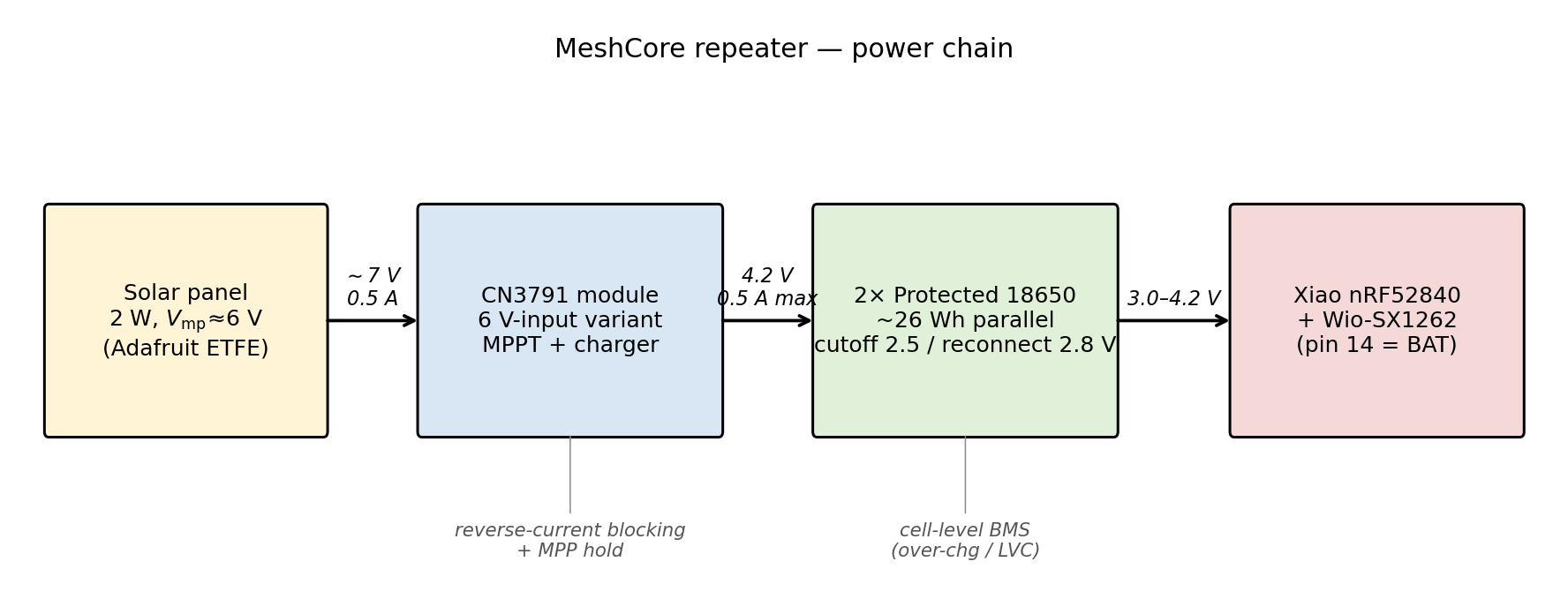
A quick glossary for the wire paths below: JST-PH is the small 2 mm-pitch keyed connector that’s standard for hobbyist battery leads; AWG is American Wire Gauge (smaller number = thicker wire, so 20 AWG is moderately thick); u.FL is the tiny coax snap-on connector for board-level RF antennas.
Wire paths, in order:
- Panel → CN3791 VIN/GND. 20 AWG silicone wire, JST-PH pigtail, through a cable gland.
- CN3791 BAT output → 2-cell 18650 holder B+/B−. Short leads inside the enclosure.
- 18650 holder → Xiao nRF52840 pin 14 (BAT) and GND. Pin 14 is the Xiao’s raw battery input; the board regulates its own 3.3 V rail internally.
- Xiao nRF52840 ← → Wio-SX1262. The Wio-SX1262 plugs into the Xiao’s stack connector — no separate wiring needed.
- Antenna (915 MHz for US, 868 for EU) → u.FL on the Wio-SX1262.
The CN3791 handles MPPT, charge termination at 4.2 V, and reverse-current blocking to the panel internally. The protected 18650 cells handle their own over-discharge / over-charge / short-circuit protection — each cell has a small BMS PCB built into the positive cap. The nRF52840 has no role in power management — it just draws from the battery rail and talks to the LoRa radio (LoRa stands for “Long Range” — it’s the low-power, long-range radio standard that MeshCore uses for the mesh).
Enclosure and mounting
A 100×70×40 mm IP65 (dust-tight, splash-resistant — fine for rain and snowmelt) junction box fits everything with room to route wires. Panel mounts on the outside, facing true south (or north in the southern hemisphere), tilted at your latitude. Two quick wins: leave a few millimeters of air gap between panel and enclosure so the panel can dump heat (a hot panel loses 20% of its output), and use a light-colored enclosure so the interior — where the battery lives — stays cooler in summer.
Mount higher than snow line if you get snow. Don’t mount where a tree branch or building corner will shadow the panel for part of the day — shadow on even 20% of a single-string panel can drop output by much more than 20%.
See Solar for IoT — “Temperature, placement, and mounting” — for the hot-enclosure math and the right way to get air flow behind the panel.
Project 2: Drone-detector node
A remote node for a MeshCore-based drone detection system. Two Xiao modules share a carrier PCB: an ESP32-C5 runs WiFi monitor mode on both 2.4 and 5 GHz to catch FAA Remote ID broadcasts (the FAA-required identification beacons every drone has to transmit), plus BLE for the Bluetooth variant of Remote ID; an nRF52840 with Wio-SX1262 relays each detection over MeshCore to a base station where it can be analyzed.
Target deployment: North Carolina tree-canopy sites with meaningful partial shade during parts of the day — which drives the 2-panel parallel-OR topology below.
Power budget
| Item | Value |
|---|---|
| ESP32-C5 in default low-power scan mode | ~50 mA avg @ 3.3 V |
| nRF52 MeshCore relay (listen) | ~10 mA avg @ 3.3 V |
| Carrier board / linear-regulator overhead | ~10 mA |
| Total average current (at 3.7 V battery rail) | ~70 mA |
| Average power | ~260 mW |
| Daily energy | ~6.2 Wh |
| Winter sun hours (35° N) with partial-shade derate | 2.5 × 0.75 = 1.9 |
| Required panel rating (rule 1) | 6.2 Wh / (1.9 × 0.40) = 8.2 W |
| Panel pick | 2× 10 W 18 V panels, parallel-OR’d |
| Battery pick | 3× unprotected 21700, 5000 mAh each in a 4-bay holder (~55 Wh nominal, ~40 Wh usable to the ~3.5 V cell floor) |
| Days of autonomy on battery alone | ~3.5–6 days (modeled from ~40 Wh usable and a ~70–130 mA average draw — the C5 dual-band scan is the big unknown; confirm with a PPK2 once built). Upgrade path: populate the 4th bay → ~4.5–8 days. |
| Worst-case charge rate | 2 A (CN3791 module limit) / 15 Ah (3 cells in parallel) \(\approx\) 0.13C |
The remote_meshcore_node firmware in use has three power
modes that it switches between automatically: a low-power scan mode by
default, a high-power mode when a drone is being tracked, and a
near-sleep mode at night, when a detection is unlikely. That’s what
keeps the ESP32-C5’s average current down. A plain continuous-scan
ESP32-C5 would draw 180–200 mA average and need a much bigger
battery.
Why 21700 and not 18650? The drone-detector node draws much more current than the repeater (70 mA average vs 10 mA), so the pack has to store substantially more energy for the same off-grid runtime. A 21700 cell at 5000 mAh holds ~43 % more energy than a 3500 mAh 18650 in only slightly more physical space (21×70 mm vs 18×65 mm). Three 21700s in a 4-bay holder give plenty of margin and leave one bay open for later expansion.
Why two panels? The parallel-OR topology
The battery and a single charger chip are shared, just like Project 1 — what’s different here is the panel side. The node uses two separate 10 W panels, each with its own Schottky diode in series, wired to the same charger input. Picture it this way:
 Panel A --> SS34 --+
                    |
                    +--> CN3791 VIN --> battery --> carrier board
                    |
 Panel B --> SS34 --+
When both panels see similar light their diodes conduct simultaneously and the currents sum at the charger input — in the easy case the topology behaves like ordinary parallel panels. The diodes earn their keep when illumination diverges: as one panel falls into partial shade, its loaded voltage drops, its diode reverse-biases, and the brighter panel keeps feeding the charger without being dragged down by its sibling.
Why bother? At a tree-canopy site, each panel spends parts of the day under a moving shade pattern. A traditional panel-in-parallel (no diode) would let the shaded panel sink current from the sunlit one. A panel-in-series would fail catastrophically when one cell is shaded — shading just 20% of a single-string panel typically drops output by more than half. The dual-Schottky diode-OR keeps most of the combined output and avoids the catastrophic loss modes of both plain-parallel wiring (a shaded panel sinking current from its neighbor) and series wiring (one shaded cell collapsing the string). It’s not a substitute for true per-panel MPPT, though — both panels that are still conducting are pinned to the charger’s single input voltage, so a panel whose ideal operating point has drifted gives up a little; with same-model, similarly-aimed panels under moving canopy shade that compromise is small.
Each SS34 drops about 0.3–0.4 V at the panel’s ~0.5 A operating current — roughly 2% of a 10 W panel’s output — and that’s well worth the harvest you recover when the two panels diverge in shade. Using half-cell panels (a modern construction where the module is wired as two parallel half-strings of half-height cells) compounds the benefit — when shade falls on one half-string, only that half drops out, not the whole panel. Most current product listings call this out as “half-cell PERC” — a high-efficiency cell architecture; either keyword in a product title is a good sign.
See Solar for IoT — “Shading and partial light” — for the full shading-loss geometry and why half-cell matters.
Bill of materials
| Part | Qty | Approx price (2026) |
|---|---|---|
| Seeed XIAO ESP32-C5 (scanner) | 1 | $8 |
| Seeed XIAO nRF52840 & Wio-SX1262 Kit for Meshtastic (SKU 102010710) | 1 | $13.49 |
2-XIAO carrier PCB (from drone-mesh-mapper
hardware/node-carrier/, JLCPCB factory-assembled) |
1 | $5 (at 10-qty) |
| 10 W 18 V half-cell glass panel (Newpowa 10W 12V Mono 10BB on Amazon, or xxrsolarpv bulk) | 2 | $26 ea / $8 ea bulk |
| SS34 Schottky diode (SMA package, 40 V 3 A) | 2 | $0.20 ea |
| CN3791 “12V variant” solar charger breakout (see note below) | 1 | $5 |
| 10 kΩ NTC thermistor (a temperature sensor; beta=3950) + thermal epoxy — bonded to one cell, wired to CN3791 TEMP pin | 1 | $1 |
| Molicel M50A / Samsung 50E 5000 mAh, unprotected (authenticated) | 3 | $27 ($9 each) |
| 4-bay 21700 parallel-wired holder with JST-PH lead | 1 | $5 |
| DW01A + FS8205A 1S BMS board (hardware backstop to the firmware soft cutoff) | 1 | $0.30 (bulk) |
| JST-PH 2-pin pigtail | 2 | $2 |
| 2.4 / 5 GHz u.FL dipole antenna (C5) | 1 | $4 |
| 915 MHz u.FL antenna (Wio-SX1262) | 1 | $4 |
| IP65 enclosure (ABS plastic, ~158×90×65 mm to fit the 4-bay holder) | 1 | $15 |
| PG7 cable glands | 3 | $3 |
| Pole mount bracket | 1 | $8 |
| Total (single node, Amazon panels) | about $130 | |
| Total (10-unit batch, xxrsolarpv panels via Alibaba — duty-paid shipping, tariffs included) | about $100/node |
The 2-XIAO carrier design lives in
hardware/node-carrier/ in the drone-mesh-mapper repo. It’s
a 65×40 mm 2-layer board written in atopile; PCB (printed circuit board)
placement and routing are scripted. Order it fabbed+assembled from
JLCPCB (the bare surface-mount components are populated at the fab),
then hand-solder 4× 1×7 through-hole female headers for the two XIAO
module sockets.
Note on the CN3791 “12V variant”
The CN3791 comes in “6V / 9V / 12V / 18V” variants on AliExpress. The numbers are confusing because they follow an old solar-industry convention: a panel with a maximum-power-point voltage around 18 V (like the ones in our BOM) has historically been sold as a “12-volt panel” because it’s designed to charge 12-volt lead-acid battery systems. The CN3791 variant labels follow the same convention — the “12V variant” is the one designed to pair with an 18 V panel charging a nominal-12 V battery system. Buy the 12V variant for the 10 W 18 V panels above.
Also verify the TEMP pad is exposed on the module before ordering a 10-unit batch — some of the cheapest AliExpress modules factory-short TEMP to GND, defeating the cold-charge-pause feature. Quick bench check with a multimeter: between the TEMP pad and GND should read open circuit, not short. If the module arrives shorted, desolder the tiny chip resistor or zero-ohm link between TEMP and GND and wire the thermistor in its place.
Wiring
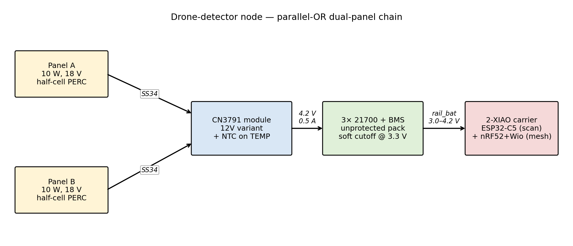
Wire paths:
- Each panel’s positive lead → through its own SS34 diode (forward direction: panel → CN3791) → both diode outputs join → CN3791 VIN. The two SS34s can live on the carrier PCB or on a small adapter board in the enclosure.
- Panel GNDs → CN3791 GND.
- CN3791 BAT → 4-bay 21700 holder B+. The CN3791 delivers charge current directly to the cell pack. The carrier has its own polyfuse (a self-resetting current fuse — pops if something shorts, and re-conducts after the short clears) and reverse-blocking Schottky diode downstream, both for USB/battery source isolation.
- Cell pack B+ / B− → DW01A+FS8205A BMS board B+ / B− pads. Keep leads short and use 22 AWG or thicker wire.
- BMS P+ / P− → JST-PH pigtail → carrier J1 (battery input). The carrier distributes this rail through its polyfuse + SS34 to pin 14 of both XIAOs.
- Thermistor → bonded to one cell (thermal epoxy or kapton + heat-sink paste) → CN3791 TEMP pad and GND. The charger auto-pauses below ~0 °C (~32 °F) and above ~50 °C (~122 °F), auto-resumes when the cell is back in range.
- ESP32-C5 D6 / D7 \(\leftrightarrow\) nRF52 D7 / D6 (serial cross-link — the same 2-wire serial bus that’s the default on every Arduino, also called UART). Wired on the carrier PCB; no external wires.
- ESP32-C5 u.FL → 2.4/5 GHz antenna. The C5 ships with a small flexible flat antenna (a thin, board-mounted printed circuit) — fine indoors. For outdoor sites, swap it for a screw-on whip antenna; the connector is the standard “RP-SMA” you see on WiFi routers. Mount it on the opposite side of the enclosure from the LoRa antenna — coupling between 2.4 GHz and 915 MHz antennas at close range costs gain on both.
- Wio-SX1262 u.FL → 915 MHz antenna.
Keeping the battery alive: two layers of protection
A Li-ion cell that drops below ~2.5 V is permanently damaged. For this project we protect the cells two ways, layered:
Layer 1 — Firmware bootlock at 3.3 V (the smart one)
Both Xiao modules check the battery voltage when they start up. If the cell is below 3.3 V, they go into a deep sleep that pulls only a few microamps — much less than the cell’s own self-discharge. They wake up automatically when the sun recharges the cell, or when you plug in USB. No user intervention, no reset button.
- The nRF52 side gets this for free from MeshCore: the
PWRMGT_VOLTAGE_BOOTLOCKfeature is enabled by default on the XIAO nRF52840 board target, with the threshold set to 3.3 V. Docs: MeshCore nRF52 power management. - The ESP32-C5 side uses the same idea in the drone-mesh-mapper scanner firmware: reads the battery through a voltage divider on the carrier, and if it’s below 3.3 V, sleeps for 30 minutes then re-checks.
Bootlocking at 3.3 V (~3.5 V at the cell, once the series diode and LDO dropout are counted) leaves the cell resting well above the 2.5 V hardware-BMS floor, at a cost of only about 30% of the pack’s capacity — not the ~50% you might guess from the voltage, since Li-ion delivers most of its energy on the flat part of the curve above 3.5 V. The long service life (years, not months) comes from shallow daily cycling — in normal solar operation the pack tops up every day and only sips a little overnight, reaching the 3.3–3.5 V bootlock floor (a deep ~70–85% discharge) only during rare multi-day dark spells. The third 21700 cell is there for that dark-stretch autonomy margin.
Layer 2 — Hardware BMS board (the backstop)
Firmware is the primary defense, but a bad flash or a firmware bug could disable it. A tiny ~$0.25 DW01A + FS8205A BMS board sits between the cell pack and the carrier as a safety net — if the cells ever actually reach 2.5 V, the BMS physically disconnects them. In normal operation the BMS does nothing; the firmware cut off hours earlier at 3.3 V.
The BMS also protects against a short-circuit across the battery output (e.g., a wiring mistake during assembly), which the firmware can’t help with.
Summary
| Cell voltage | What happens |
|---|---|
| 3.3 V | Firmware bootlock on both Xiao modules disconnects the load; both modules enter deep sleep, wake on recovery or USB. |
| 2.5 V | Hardware BMS physically disconnects the pack — should never happen in practice because the firmware cut off hours earlier, but catches firmware failures and wiring mistakes. |
Project 1’s repeater doesn’t have a separate BMS board in its BOM because the protected 18650 cells have one built into the cell’s positive cap — same DW01A-class protection, just packaged inside the cell. MeshCore’s firmware bootlock still runs as the primary layer there too. Both architectures layer a software cutoff over a hardware cutoff; they just package the hardware side differently.
Enclosure and mounting
Panels mount on top of the enclosure or on a separate bracket above it; the node sits inside with a cable gland for each antenna and one for the panel pigtail. The two panels want to be roughly co-planar but not touching — a small air gap between them (and between panels and the enclosure) helps both heat dissipation and makes the diode-OR useful, since they’ll see slightly different shade patterns through the day.
NC tree-canopy context: favor higher-up mounting where afternoon sun reaches through a gap even in leaf-out season, and plan to revisit the site once after leaf-out to check whether panel orientation still makes sense. A sub-8 Wh daily budget at 70 mA average is thin enough that a site that looked fine in winter can go dark in June.
Enclosure, mounting, weatherproofing (common to both)
IP rating
IP65 is plenty for both projects — it’s dust-tight and rated against low-pressure water jets, which covers rain, snowmelt, and everything short of a pressure washer. Plastic junction boxes from the electrical aisle of any hardware store meet this, and cheap Amazon project enclosures marketed as “IP65 / IP67 waterproof” are fine in practice.
Sealing
Every wire that enters the enclosure is a potential leak path. Two ways to handle this correctly:
- Cable glands (PG7 / PG9). One per cable, threaded through a drilled hole, with a rubber gasket that compresses around the wire. Works well, cheap, reliable.
- Silicone sealant on existing grommets. If your enclosure came with rubber grommets, fill them with RTV silicone around the wire after routing. Cruder but works.
Don’t just drill a hole and run a wire through. It’ll leak within a month.
Orientation and tilt
Panel faces the equator (south in the northern hemisphere), tilted at an angle roughly equal to your latitude. For winter-dominated designs like these, tilt 5–15° steeper than latitude — it loses a little summer harvest in exchange for more winter harvest, which is when you need it. At 35° N, that’s 40–50° from horizontal.
A pole mount with a U-bolt bracket is simple and lets you adjust tilt once installed. For rooftop installation, the panel can strap to an existing structure; for pole mount, a 1.5-inch galvanized pipe driven into the ground or clamped to a fence post works.
Heat
A black plastic enclosure in direct sun can hit 60–70 °C (140–160 °F) inside even on a mild day. That bakes the battery. Three easy fixes stacked:
- Light-colored enclosure (white or grey).
- Air gap behind the panel (5–10 mm spacers, not flush).
- Mount the enclosure in shade if you can, with the panel separate.
The panel itself loses output when it heats up (about 0.4% per °C / 0.22% per °F above the 25 °C / 77 °F lab nameplate), so even the panel wants air behind it. Two gains for one intervention.
See Solar for IoT — “Temperature, placement, and mounting” — for the full heat discussion and the Nominal Operating Cell Temperature rating on datasheets (a more realistic rating than the lab nameplate).
Antenna placement
The MeshCore repeater has a single 915 MHz antenna — just mount it clear of metal, at least a quarter wavelength (about 8 cm at 915 MHz) from any large metal surface or bracket.
The drone-detector node has two antennas (2.4/5 GHz for the ESP32-C5, 915 MHz for the Wio-SX1262). They’re far apart in frequency so they don’t cross-talk much, but you still want them on opposite sides of the enclosure so the metal parts inside (battery, the metal layers on the circuit board) don’t shadow either one. Don’t let either antenna sit in the panel’s shadow — that shifts with the sun during the day and is easy to overlook.
Sourcing lithium cells — buy from the brand’s own website
The battery is the easiest part of the build to get wrong. The 18650 and 21700 markets are polluted with counterfeits — no-name cells relabeled as Samsung or Panasonic, or “4000 mAh” cells that actually hold 800 mAh. You can’t eyeball the difference without a battery tester.
- AliExpress, eBay, and third-party Amazon resellers frequently ship fake or rewrapped cells. “Ultrafire,” “TrustFire,” and any other “-fire” brand is always inflated-claim or no-name.
- Amazon is risky even from the brand’s own storefront, because Amazon’s FBA system commingles inventory by UPC: when a counterfeit seller drops fakes into the bin under the same UPC as a real brand, Amazon may ship whichever is closest to the buyer — even if you ordered from the brand’s storefront. Amazon has announced commingling will end March 31, 2026, but until that takes effect (and the supply chain settles), the safer path is to skip Amazon for cells and order direct from the seller’s own website.
- Specialist retailers — order from their own websites, not Amazon: Orbtronic (orbtronic.com), Illumn (illumn.com), Liion Wholesale (liionwholesale.com), IMR Batteries (imrbatteries.com), Battery Junction (batteryjunction.com) in the US; Nkon (nkon.nl) in Europe; Fogstar (fogstar.co.uk) in the UK. All stock both 18650 and 21700, protected and unprotected.
- Good 18650 cells (Project 1): Samsung INR18650-35E or Panasonic NCR18650GA, both 3500 mAh. Protected variants add $2–3 and 3–4 mm length. Get protected — it’s the simplest way to get a built-in hardware BMS for the tutorial build.
- Good 21700 cells (Project 2): Samsung INR21700-50E, Molicel INR21700-M50A, or Panasonic NCR21700A from a specialist retailer. Skip the cheap EBL 5000 mAh cells you’ll see on Amazon — their capacity results are inconsistent, and Amazon’s commingling makes any Amazon cell a gamble anyway. Buy an authenticated 21700 from a specialist; the few-dollar premium is rounding on the full node cost. For Project 2 use unprotected cells: the firmware bootlock plus the external DW01A BMS board handles low-voltage cutoff.
Buying the DW01A+FS8205A BMS board (Project 2 only)
The hardware safety-net for the drone-detector pack. You need one 1S board per node. They’re pennies in bulk.
- Search: AliExpress (or Amazon) for “1S 3.7V 3A BMS 18650”. You want a tiny ~29 × 4.5 mm PCB with four solder pads labeled B+, B-, P+, P-. A 10-pack typically runs $2–3, about $0.20–0.30 per node. Buy extras.
- Must be 1S. Do not buy anything labeled 2S, 3S, 4S, or higher — those boards balance-protect series sub-groups. Wiring a 2S board across a parallel-only pack will damage cells or disconnect them. Always confirm “1S” in the title.
- Preferred chipset: DW01A (the protection IC, decides when to disconnect) + FS8205A (a dual MOSFET — basically two electronic switches in one chip, the actual disconnector). The HYCON HY2110 (the 1-cell DW01A-equivalent) at ~2.4 V cutoff is also fine — but don’t confuse it with the HY2120, which is the 2-cell (2S) sibling; a 2S part on a 1S pack won’t protect correctly. XP3101 at 2.3 V is borderline — avoid if you can see it on the silkscreen of the product photo. Sellers often omit the chipset from the title; look at the photos for the IC markings.
- Seller rating: AliExpress seller with 4.7 stars or higher. Otherwise you’re back in “is it actually what I ordered” territory.
- Wiring: 22 AWG or thicker, short leads. Pack
B+/B-→ BMSB+/B-, then BMSP+/P-→ JST-PH pigtail → carrier’s battery input. - Electrical overhead you can ignore: each FS8205A MOSFET has about 20 mΩ of channel resistance, and the two sit in series in the current path, so at a 500 mA burst the BMS adds ~20 mV of drop — still negligible. The DW01A’s own quiescent (idle) draw is ~3 µA — that’s 26 mAh/year, well inside the cells’ own 2 %/month self-discharge.
- Heat: none. The BMS dissipates under 50 mW at this project’s load. No heatsink, mount anywhere inside the enclosure.
Pitfalls checklist
A short, ordered list of the mistakes that actually kill deployments:
- Sizing from the nameplate. The panel’s printed rating is a lab number. Multiply by 0.40 before you design.
- Skipping the worst-month check. Summer gives you 2× the harvest of winter at mid-latitudes. If December works, the rest of the year works.
- Panel in a shadow you didn’t notice at install. Walk the site at morning, noon, and afternoon. Mark where the shadow edge falls. Expect worse after leaf-out.
- No cutoff, or cutoff with no hysteresis. Always cutoff + reconnect with at least 400 mV hysteresis for Li-ion.
- No buffer capacitor across the battery rail. If your load pulls short bursts (LoRa transmit, WiFi transmit), a small battery alone can sag under the burst. Add a buffer capacitor — total 100–470 µF, mixing a ceramic capacitor for fast bursts with an electrolytic capacitor for the bulk — near the board’s power input.
- Wrong CN3791 variant. The 6 V, 9 V, 12 V, and 18 V modules look identical — the only difference is the resistor divider that sets the maximum-power-point voltage. Buy the one that matches your panel’s Vmp.
- Panel wired to battery without a charger. Damages the cell on the first sunny day. Always have a charger chip.
- Assumed IP67 enclosure but the cable gland wasn’t tightened. Common. Tighten until the grip ring deforms visibly.
- Mounting the panel flush against a black enclosure. 40 °C (~70 °F) above ambient is common. Leave an air gap.
- Panel and battery on the same side of the world as the shade-side antenna. Not really a pitfall but a thing you’ll notice during your first deploy.
- Counterfeit cells, even from “reputable” Amazon storefronts. Amazon’s FBA inventory is commingled by UPC until March 2026, so a real-brand listing can ship a fake from the same bin. Buy direct from a specialist’s own website (not Amazon, not AliExpress). See § Sourcing lithium cells.
- (Project 2) CN3791 module with the TEMP pin factory-shorted to GND. Defeats the cold-charge-pause feature. Bench-check with a multimeter before ordering the batch.
- (Project 2) Treating the firmware bootlock as the whole safety story. A bad flash or bug could disable it. Always layer the ~$0.25 DW01A+FS8205A BMS as the hardware backstop. Don’t skip the BMS to save a quarter.
- (Project 2) Buying a 2S/3S BMS by mistake. Only 1S boards protect a parallel-only pack correctly. Confirm “1S” in the title before clicking buy.
Troubleshooting
When a node misbehaves it’s almost always one of a handful of things. Work down the list.
| Symptom | Likely cause | What to check |
|---|---|---|
| Battery never charges, even in full sun | Wrong CN3791 variant, panel voltage outside the charger’s range, or a cold solder joint on the panel lead | Measure panel voltage in sun; confirm it exceeds battery voltage and sits inside the module’s input range; reflow the VIN/GND joints |
| Charges fine on the bench, dead after a week outside | Undersized for the worst month, or a shadow you missed at install | Recheck Rule 1 with December sun hours; walk the site morning, noon, and afternoon and watch where the shadow edge falls |
| Boots, runs a few seconds, shuts off, repeats | Brown-in loop — battery low, cutoff without enough reconnect hysteresis | Charge the cell fully and retest; confirm the reconnect threshold sits well above the cutoff (Rule 3) |
| Won’t boot after a cold, cloudy stretch | Cell sat below the firmware bootlock and hasn’t recovered, or charging is paused by the cold-charge cutoff | Give it a sunny day or top the cell up over USB; below 0 °C the CN3791 pauses charging by design |
| Battery slowly dies over weeks with the panel connected | Reverse leakage at night (rare with these chargers), or a parasitic draw you didn’t budget for | Measure current out of the battery in the dark; confirm a charger — not a raw panel — is wired in |
| Poor radio range | Antenna too close to metal, sitting in the panel’s shadow, or the two antennas coupling on Project 2 | Move the antenna a quarter wavelength off metal; keep the 915 MHz and 2.4/5 GHz antennas on opposite sides |
| (Project 2) Cold-charge pause never triggers | TEMP pad factory-shorted to GND on the CN3791 module | Meter TEMP to GND — it should read open, not short (see the note in Project 2’s BOM) |
If none of these fit, log battery voltage and panel voltage over a full day. That trace usually points straight at the problem.
Further reading
- Solar for IoT — A Practical Reference — the physics-first companion document, distributed alongside this one. Everything above is a distillation; go there for the why.
- drone-mesh-mapper repo (github.com/colonelpanichacks/drone-mesh-mapper) — firmware, base-station web app, and the 2-XIAO carrier PCB.
- MeshCore documentation — node firmware, mesh network setup, range-testing methodology.
- NREL PVWatts — plug in a US ZIP code, get monthly peak-sun-hour estimates and a sizing sanity check.